Rolling

GMan and I took a rolling class. The start was more of a how to gracefully fall out of your kayak, but toward the end I was at least getting the mechanics down.

The most important thing I learned was its all in the hips! No strength involved, all in the hips.

Now….for an Irish guy with two left feet and (ask my wife) no sway in the hips, it was work, but fun work. Perhaps this will improve my dancing! Hmmmm…na, not a chance. You know what say about white guys and dancing…..well the Irish take that to a new level. Heck, someone has to hold up the bar!

All in all is was a great class. Check out Charles River Canoe and Kayak.

The following at pictures from last weeks trek on the Concord River.

20130621-202342.jpg

GMan found a baby otter out for a swim. It climbed up on his paddle for a rest.

20130621-203014.jpg

Warp speed Mr. Sulu! Pano and AutoStitch.

20130621-203440.jpg

Baddacook Pond

GMan and I took a quick cruse around Baddacook Pond this evening. It a small pond in Groton MA off RT 40 and few other back roads.

20120907-194634.jpg

It has lots of parking with room for at least 8 of possibly 10 cars. You can also park on the side of the road.

20120907-194820.jpg

Access is very easy as the ramp is in good shape. Simply unload, drop your kayak in the water and push off.

20120907-195500.jpg

On the pond.

20120907-195556.jpg

GMan all smiles.

20120907-195816.jpg

Low sun equals great light.

20120907-201200.jpg

Pano 1.

20120907-201237.jpg

Pano 2.

20120907-201312.jpg

Pano 3.

20120907-201337.jpg

Installing a bilge pump 4

Made the finishing touches on the bilge pump installation. Just in time for the end of summer but I hoping to extent the kayaking season as long as possible.

I did a dry run to find the best position to install the hose from the pick -up. Basically it involved sitting in the kayak and moving the hose about. The end result can be seen in the following images.

20120902-210804.jpg

In the above image you can see the hose running forward on the starboard side just above the peg rail. I found some nylon pipe hangers in the hardware store and utilized the bungee/lines hold down as the forward clamping positions.

20120902-211622.jpg

Then the hose goes between the seat and hull.

20120902-211727.jpg

Then turns and is clamped to the bulk head behind the seat in two places. I used stainless steel hardware everywhere and on the bulkhead I also used rubber washers on both sides to keep water out of the day hatch.

20120902-212109.jpg

The pick-up strainer is simply sitting against the hull and held in place by the clamps. If all goes well I hope to take it for a wet run tomorrow. Not sure if I’ll intentionally swamp it, but I will test it out one way or another.

Installing a bilge pump 3

Four hours later the frame was ready and it took twice as long to get everything installed. The only way to get the assemble in place was to attach the frame to the pegs and use wire ties to keep the springs in compression, holding the overall unit together. However, I could not get the peg rail into the kayak while on the assembly, so I slipped the rails off, inserted everything into the kayak, then put the rail back on and gently pushed and pulled until it all went into place. Remember that 10lbs of you know what in a 5lbs bag statement…..well, I was living it for sure.

Here’s the frame in place and you can see the thru-the-hull fitting, hose and one way valve behind it. The space was filling up fast.

This image shows the pump with all hoses connected ready for installation. By the way the pump is held in place with four stainless steel threaded rods, with nuts on the front and back side of the pump and frame to hold everything in place and allow forward and back adjustment.

Finally the entire frame, pump and hoses in place. It was a bit of a challenge hooking everything up, but it all went in and it will take a bit of work to get it out. Like I said this is an optional extra that will be sold with the boat if I ever decide to sell that is.

I still have a little more work on securing the hoses and installing the strainer on the pick up end of the hose. The strainer will be behind the seat. Here’s a quick video demonstrating of the pump in action in dry land. I simply placed the garden hose in the boat, turned on the water and started pumping. As other videos I found on the pump in this sort of application, the water does not fly out like a faucet, but it does work very well.

Installing a bilge pump 2

From my welding days I have always to work with aluminum. I welded a lot of different material from low grade carbons to stainless and some exotics like titanium. I figured if I was going to keep the weight of this project down aluminum would be the way to go. Another trip to Home Depot produce the material I needed. I has an idea in my head of how I wanted the frame to work, so it was a matter of utilizing the stock on hand at the store. I picked up some 1″ by 1″ and 3/4″ by 3/4″ hollow square tube, 1 1/2″ x 1/8″ flat, 3/4 by 1/8″ flat and 3/4″ x 1/8″ angle. I knew I wanted adjustment back and forth and side to side and the rest could be worked out on paper, and later transferred to Revit (3D Parametric drawing application).

Here’s the raw stock and my chop saw.

This is the best set up for working on inside of your kayak. Simple invert on a few saw houses, I raised the back end and it gave me more movement. I hooked up a shop lamp inside the kayak for light and I finally got some use of my wheelie shop seat.

My welding machine that kept tripping the breaker. Unfortunately the breaker was sized for my MIG welder and this TIG machines came after the supply was installed and it consumes a few more amps.

As with any new architectural project this one started with the existing conditions.

20120824-192250.jpg

20120824-192600.jpg

From here I doodled a bit then entered everything into Revit. I wanted to get a idea of what the overall size of the space considering the amount of stuff I was about to cram into it. This reminded me of my last welding job. The company makes chemical separation equipment and generally we needed to get 10 LBS of you know what into a 5LBS bag! This project was going to be the same.

Here’s the space, overall its 11 1/4″ tall and 17 1/2″ wide.

Here’s the pump in the space. Remember all the picture were taken upside down and inverted for this blog, so the pump looks like its floating!

After a few iterations in Revit I settled on the following. The 1″ x squared tube would form the main frame and adjustable legs would stick out from either side. Early on I decided that connecting to the rear of the foot pegs would mean that if I grow 6 or so inches the pump will simply adjust with me! Coming back to reality if a shorter person wanted to try out my boat they can and if they need to pump out they can do that also. Long range thinking was helping to drive this decision and if I even sell the kayak I’ll simply list the pump and an optional extra.

Here’s the final drawing of the pump and frame. I came up with the notion of inserting compression springs in the inner tube that would center the pump between the foot pegs. As the inner tube fit inside the outer tubes and moved freely to allow the pegs to be move forward and aft, the springs would force the pump assembly to center all the time. Yet another trip to the hardware store located the springs and few other odd and ends I needed.

This image shows the pump assembly and foot pegs/rails. As I’m sure you know overkill is my middle name and I don’t recommend you model every nut and bolt when using Revit to design a building, but you can get away with doing so on the project this small.

The next three images show the bow, stern and a 3D view of the pump assemble, peg, rails and yes a portion of the kayak (in proper colors).

Installing a bilge pump 1

A few weeks ago I posted on installing a compass in my kayak. This month I installed a bilge pump. I actually started when I put in the compass, but saved the post until now. As we say in the old sod “may as a well get hung for a sheep as a lamb”. In other words if I was going to cut one hole in my kayak I may as well cut two and get all my projects over with. The pump really only needed one hole, an outlet, for what is commonly known as a thru-hull-fitting. This is where the water goes out and in theory none comes back in! I did a search and found the following links with information on similar projects. As always I like to see how other people did it before I proceed.

My Adventures In Foot Pumps

This is a great blog and I found it very useful. The photo were very helpful and gave a good sense of what I could expect when installing mine.

Installing a foot operated bilge pump

Nice PDF on the entire install process. Many different kayaks are shown, but all are related. I also read that turning the kayak upside down and working from under it is the only way you can actually do this sort of project.

Hybrid kayaks australia

This company only talks about installing a pump in a new kayak, but what a sweet looking boat. If I ever get to Australia I will buy one!

The choice of pump came down to two (very quickly). One was out of the UK and way too much money, the other was from down the road in Rhode Island. The choice was easy and I pick up the phone and called The Bosworth Company in East Providence, RI. This was clearly a small manufacturing firm how wanted to take care of every customers needs. I was greeted like a long lost friend and once I explained what I wanted to do the sales person filled me in on all details and make several recommendations. I ended up ordering the Guzzler “450” Foot Button Pump, some hose, a one way valve and a strainer. A few days later it all showed up (very well wrapped) from the UPS man.

Drilling another hole in my kayak. Tools of the trade and the ends result.

The through the hull fitting was the correct size for the hose I was using, but the shoulder was little thick so I need to make a spacer so the lock nut would tighten down on that kayak hull. Yet another trip to the hardware store produced a PVC fitting that was a nice fit on the thread and big enough so the nut would have plenty to bite on.

This image shown the thru-hull-fitting (right), its nut (bottom) and the PVC spacer fitting. Note the shoulder on the fitting where the thread ends toward the top.

20120824-194449.jpg

Here’s the fit up and finished product.

Kayak compass install

I picked up some stainless steel 8-32 screws and self locking nuts. The machine screws that came with the compass would most likely have worked fine, but fine never did it for me.

Here’s the fit up.

20120714-232538.jpg

Mounting holes drilled.

20120714-232708.jpg

I figured that having screw head in the forward hatch was better than the threads and nuts ripping at every dry bag I’ll ever put in there. I put a ring of marine sealant around the screw heads and inserted them up through the recess mount. Then I put another ring of sealant around the top. In this case more is better as I don’t want water in front hatch if I can help it.

20120714-233417.jpg

The finished product.

20120714-233627.jpg

Kayak compass mount

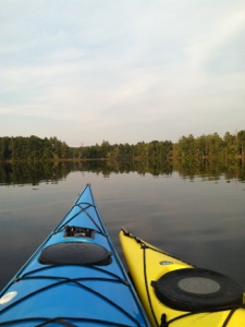
Some time ago I kicked around the idea of installing a compass in my kayak. You know, for that tran Atlantic trip I’ll be taking some day! In all honesty that may never happen, but a more realistic use may be some coastal treks or larger lakes. Unlike many roto type kayaks mine did not come with a compass recess per molded into the hull.

The first order of business was finding one. I found what I needed at Reed Rockpool North America and a few other goodies which I ordered. Given that this was a PayPal type interaction I figured I’d be waiting a few weeks for my gear. After three weeks I decided it was time to email. Another week passed and no word then I received a reply from a lad named Ray. Turns out they had no spare paddle holder or recessed compass mounts and the owner (Chris) had the machine for making new decals on the road with him. Mind you on the road was in Alaska! I asked the Ray to call me and talk about what we can do and where we can go from here.

Ray replied and said he’d call the following day. He did and informed me that the web site was in need of updating…..as it should say whats in and whats not in, really I thought to myself and he also said the owner would not be back for another two weeks. Hmmm….I asked for a full refund, go it and asked that the owner contact me when he returned.

Three weeks passed, then four. On the fifth I decided to email again. This time mailed Chris via the still outdated web site and Ray. No response from the Chris, but Ray said that my recessed compass mount was sitting on a work bench in Chris’ shop. Great I said, please have Chris contact me as I wanted to talk about the decals. Okay was the reply. Many more weeks go by and no word. Once again I emailed Ray and he said “Chris was waiting to hear from you”! Hmmm…So at this point I had a compass sitting on my desk acting as a paper weight, a compass recess sitting on a bench the other side of the country and a business owner who either has his head so far up his ass that he has no idea how to run a business, or he’s so busy he can’t enen think straight and reply to any of mt emails.

As Clark Gable said “frankly my dear, I don’t give a dam”. I figured what did I have to loose…..I’d just order it again on line and hope that some day I’d get it. At least if he did not show up I could send him a few more email he surly ignore and them I’d be rightly pissed.

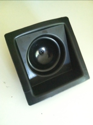
Well finally after a few months, thirty odd email, two phones calls, one refund and countless occasions when I considered buying a kayak with a per installed the mount showed up.
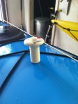
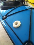
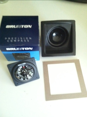
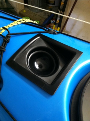
Here it is.

20120714-224115.jpg

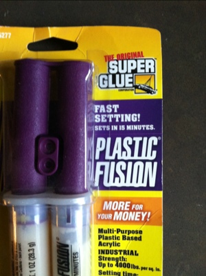
The kit also came with epoxy.

20120714-224341.jpg

According to the video on YouTube in which Chris demonstrates installing the mount he states that the kit will include a template for cutting the hole correctly, well guess what, mine did not have one! I made my one.

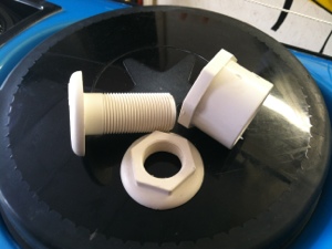
Here’s everything prior to starting installation.

20120714-224914.jpg

Go watch the video for a live version. However, here are a few shots on my install.

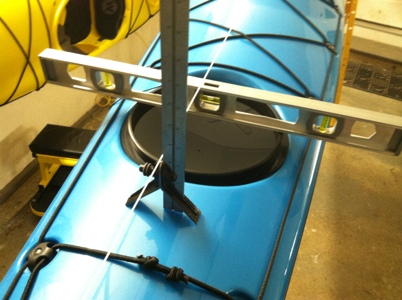
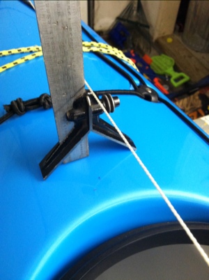
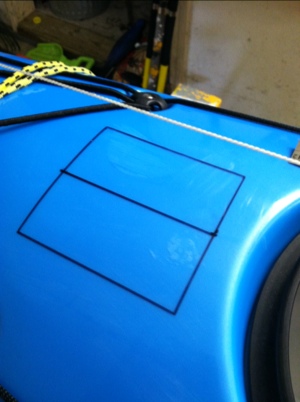
String to find center and a level for good measure. For those of you who know me I cant do 1/2 measures!
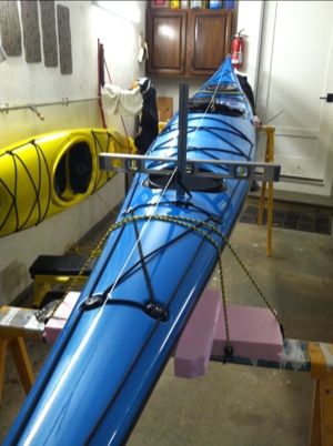
20120714-225310.jpg

Finding center.

20120714-225547.jpg

20120714-225603.jpg

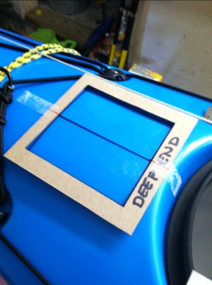
Template in place and lines transferred. The “Deep End” was reminder to install the mount in correct orientation.

20120714-230533.jpg

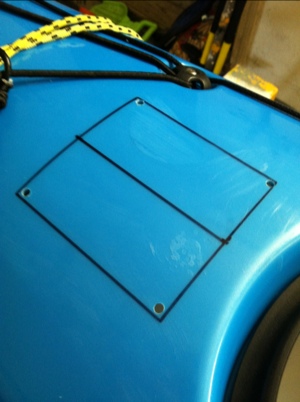
Laid out as we say in the welding trade.

20120714-230644.jpg

Corners drilled.

20120714-230729.jpg

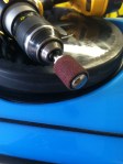
Rough cut (by jig saw).

20120714-230828.jpg

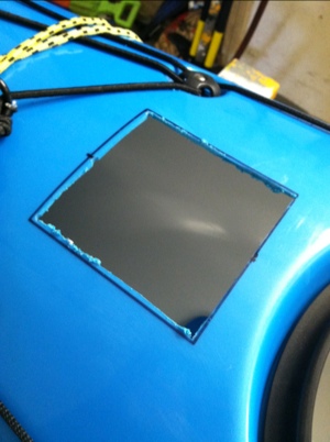
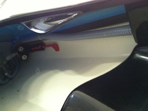
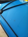
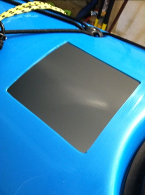
Finished hole. It was at this point that you don’t want to regret your decision!
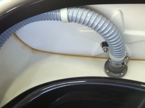
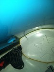
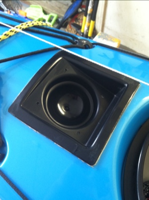
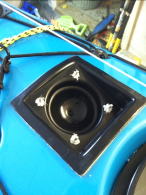
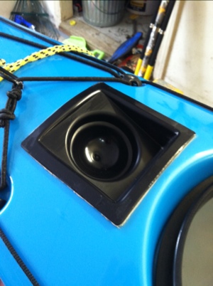
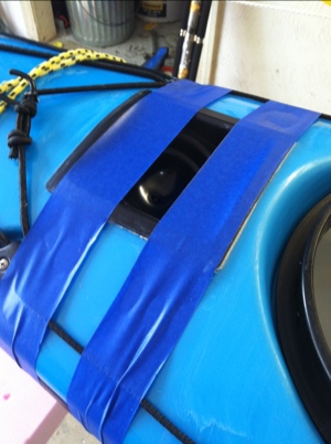
20120714-231100.jpg

Final fit up.

20120714-231151.jpg

A couple over sized band aids to hold it all in place.
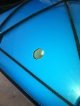
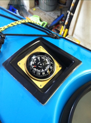
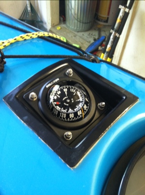
20120714-231322.jpg

Completed mount.

20120714-231419.jpg

iPhone dry bag update

As may have read while camping we spend a great deal of time on the water. I really put the OB iPhone bag through the ringer and it came out dry every time. It got splashed a lot, dropped in the water twice as I was getting out of my kayak and it sat on the bottom of my boat for extended periods.

What sealed the deal for me was when we were practicing wet exists and self rescues. I placed the OB (with phone) under the bungee so it would not be flopping around. I must have flipped my boat ten times and showered it with water in my failed attempts to get my sorry you know what back in my boat, and not a single drop of water got in!

Go here for details.