In honor of my mom Honor Catherine Quinn (Coyle)

Miscellaneous ramblings of an Irish American
In honor of my mom Honor Catherine Quinn (Coyle)
Happy Friday….glad I made it.

Spotted this one at a stop light.

Passed this gem on the highway….no I was not driving!

This is how I remember my spot….hey I know what you’re thinking, just remember it, but why bother.

Bike day at GCS and the JMan got started early. Here he is taking a spin in the hallway.
Four hours later the frame was ready and it took twice as long to get everything installed. The only way to get the assemble in place was to attach the frame to the pegs and use wire ties to keep the springs in compression, holding the overall unit together. However, I could not get the peg rail into the kayak while on the assembly, so I slipped the rails off, inserted everything into the kayak, then put the rail back on and gently pushed and pulled until it all went into place. Remember that 10lbs of you know what in a 5lbs bag statement…..well, I was living it for sure.
Here’s the frame in place and you can see the thru-the-hull fitting, hose and one way valve behind it. The space was filling up fast.

This image shows the pump with all hoses connected ready for installation. By the way the pump is held in place with four stainless steel threaded rods, with nuts on the front and back side of the pump and frame to hold everything in place and allow forward and back adjustment.

Finally the entire frame, pump and hoses in place. It was a bit of a challenge hooking everything up, but it all went in and it will take a bit of work to get it out. Like I said this is an optional extra that will be sold with the boat if I ever decide to sell that is.


I still have a little more work on securing the hoses and installing the strainer on the pick up end of the hose. The strainer will be behind the seat. Here’s a quick video demonstrating of the pump in action in dry land. I simply placed the garden hose in the boat, turned on the water and started pumping. As other videos I found on the pump in this sort of application, the water does not fly out like a faucet, but it does work very well.
From my welding days I have always to work with aluminum. I welded a lot of different material from low grade carbons to stainless and some exotics like titanium. I figured if I was going to keep the weight of this project down aluminum would be the way to go. Another trip to Home Depot produce the material I needed. I has an idea in my head of how I wanted the frame to work, so it was a matter of utilizing the stock on hand at the store. I picked up some 1″ by 1″ and 3/4″ by 3/4″ hollow square tube, 1 1/2″ x 1/8″ flat, 3/4 by 1/8″ flat and 3/4″ x 1/8″ angle. I knew I wanted adjustment back and forth and side to side and the rest could be worked out on paper, and later transferred to Revit (3D Parametric drawing application).
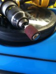
Here’s the raw stock and my chop saw.

This is the best set up for working on inside of your kayak. Simple invert on a few saw houses, I raised the back end and it gave me more movement. I hooked up a shop lamp inside the kayak for light and I finally got some use of my wheelie shop seat.

My welding machine that kept tripping the breaker. Unfortunately the breaker was sized for my MIG welder and this TIG machines came after the supply was installed and it consumes a few more amps.

As with any new architectural project this one started with the existing conditions.


From here I doodled a bit then entered everything into Revit. I wanted to get a idea of what the overall size of the space considering the amount of stuff I was about to cram into it. This reminded me of my last welding job. The company makes chemical separation equipment and generally we needed to get 10 LBS of you know what into a 5LBS bag! This project was going to be the same.
Here’s the space, overall its 11 1/4″ tall and 17 1/2″ wide.

Here’s the pump in the space. Remember all the picture were taken upside down and inverted for this blog, so the pump looks like its floating!

After a few iterations in Revit I settled on the following. The 1″ x squared tube would form the main frame and adjustable legs would stick out from either side. Early on I decided that connecting to the rear of the foot pegs would mean that if I grow 6 or so inches the pump will simply adjust with me! Coming back to reality if a shorter person wanted to try out my boat they can and if they need to pump out they can do that also. Long range thinking was helping to drive this decision and if I even sell the kayak I’ll simply list the pump and an optional extra.
Here’s the final drawing of the pump and frame. I came up with the notion of inserting compression springs in the inner tube that would center the pump between the foot pegs. As the inner tube fit inside the outer tubes and moved freely to allow the pegs to be move forward and aft, the springs would force the pump assembly to center all the time. Yet another trip to the hardware store located the springs and few other odd and ends I needed.

This image shows the pump assembly and foot pegs/rails. As I’m sure you know overkill is my middle name and I don’t recommend you model every nut and bolt when using Revit to design a building, but you can get away with doing so on the project this small.

The next three images show the bow, stern and a 3D view of the pump assemble, peg, rails and yes a portion of the kayak (in proper colors).


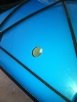
A few weeks ago I posted on installing a compass in my kayak. This month I installed a bilge pump. I actually started when I put in the compass, but saved the post until now. As we say in the old sod “may as a well get hung for a sheep as a lamb”. In other words if I was going to cut one hole in my kayak I may as well cut two and get all my projects over with. The pump really only needed one hole, an outlet, for what is commonly known as a thru-hull-fitting. This is where the water goes out and in theory none comes back in! I did a search and found the following links with information on similar projects. As always I like to see how other people did it before I proceed.
This is a great blog and I found it very useful. The photo were very helpful and gave a good sense of what I could expect when installing mine.
Installing a foot operated bilge pump
Nice PDF on the entire install process. Many different kayaks are shown, but all are related. I also read that turning the kayak upside down and working from under it is the only way you can actually do this sort of project.
This company only talks about installing a pump in a new kayak, but what a sweet looking boat. If I ever get to Australia I will buy one!
The choice of pump came down to two (very quickly). One was out of the UK and way too much money, the other was from down the road in Rhode Island. The choice was easy and I pick up the phone and called The Bosworth Company in East Providence, RI. This was clearly a small manufacturing firm how wanted to take care of every customers needs. I was greeted like a long lost friend and once I explained what I wanted to do the sales person filled me in on all details and make several recommendations. I ended up ordering the Guzzler “450” Foot Button Pump, some hose, a one way valve and a strainer. A few days later it all showed up (very well wrapped) from the UPS man.
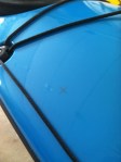
Drilling another hole in my kayak. Tools of the trade and the ends result.


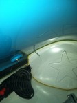


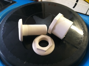
The through the hull fitting was the correct size for the hose I was using, but the shoulder was little thick so I need to make a spacer so the lock nut would tighten down on that kayak hull. Yet another trip to the hardware store produced a PVC fitting that was a nice fit on the thread and big enough so the nut would have plenty to bite on.
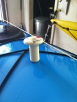
This image shown the thru-hull-fitting (right), its nut (bottom) and the PVC spacer fitting. Note the shoulder on the fitting where the thread ends toward the top.
Here’s the fit up and finished product.


Plate –> HISSY
Car –> honda FIT
Thanks B

Plate = NANTOT (Nantucket?)
Car = Range Rover

Sunday’s are made for ice cream.


We also came across the “Lesser spotted hairy thing”

I found my great aunt Essie in the 1940 Census. See lines 19 thru 26 in the below.